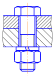
Bolts vs. screws
The distinction between a bolt and a screw is commonly misunderstood. There are several practical differences, but most have some degree of overlap between bolts and screws.
The defining distinction, per Machinery's Handbook,[2] is in their intended purpose: Bolts are for the assembly of two unthreaded components, with the aid of a nut. Screws in contrast are used with components, at least one of which contains its own internal thread, which even may be formed by the installation of the screw itself. Many threaded fasteners can be described as either screws or bolts, depending on how they are used.
Bolts are often used to make a bolted joint. This is a combination of the nut applying an axial clamping force and also the shank of the bolt acting as a dowel, pinning the joint against sideways shear forces. For this reason, many bolts have a plain unthreaded shank (called the grip length) as this makes for a better, stronger dowel. The presence of the unthreaded shank has often been given as characteristic of bolts vs. screws,[3] but this is incidental to its use, rather than defining. The grip length should be chosen carefully, to be around the same length as the thickness of the materials, and any washers, bolted together.[4] Too short places the dowel shear load onto the threads, which may cause fretting wear on the hole. Too long prevents the nut from being tightened down correctly. No more than two turns of the thread should be within the hole.[4]
Where a fastener forms its own thread in the component being fastened, it is called a screw.[2] This is most obviously so when the thread is tapered (i.e. traditional wood screws), precluding the use of a nut,[2] or when a sheet metal screw or other thread-forming screw is used.
A screw must always be turned to assemble the joint. Many bolts are held fixed in place during assembly, either by a tool or by a design of non-rotating bolt, such as a carriage bolt, and only the corresponding nut is turned.[2]
Bolt types
- Anchor bolt - Bolt designed to allow objects to be attached to concrete. The bolt head is usually placed in concrete before it has cured, leaving the threaded end exposed.
- Arbor bolt - Bolt with a washer permanently attached and reversed threading. Designed for use in miter saw and other tools to auto tighten during use to prevent blade fall out.
- Carriage bolt - Bolt with a smooth rounded head and a square section to prevent turning followed with a threaded section for a nut.
- Elevator bolt - Bolt with a large flat head used in conveyor system setups.
- Hanger bolt - Bolt that has no head, machine threaded body followed by a wood threaded screw tip. Allow nuts to be attached to what is really a screw.
- Hex bolt - Bolt with a hexagonal head and threaded body. Section immediately under head may or may not be threaded.
- J bolt - Bolt shaped like the letter J. Used for tie downs. Only the non curved section is threaded for a nut to be attached.
- Lag bolt - Not a true bolt. Hex bolt head with thread screw tip for use in wood.
- Rock bolt - Used in tunnel construction to stabilize walls.
- Sex bolt or Chicago Bolt - Bolt that has a male and female part with interior threads and bolt heads on either end. Commonly used in paper binding.
- Shoulder bolt or Stripper bolt - Bolt with a broad smooth shoulder and small threaded end used to create a pivot or attachment point.
- U-Bolt - Bolt shaped like the letter U where the two straight sections are threaded. A straight metal plate with two bolt holes is used with nuts to hold pipes or other round objects to the U-bolt.
Solidworks trick (create screw of bolt using cosmetic treads)
So many trick to create screw of bolt using solidworks, i try to create screw of bolt using very simple steps without create 2D spiral and helix design, without triangle and swept cut. you can click this link to see my trick https://www.youtube.com/watch?v=6WpTVCzAO4c


Comments
Post a Comment