Solidworks tricks for beginner
Solidworks can build everything 3D model, you can learn trick step by step following my video to create 3D model wich you want. First time you must know about projection of drawing to create engineering drawing.
Multiple views and projections
In most cases, a single view is not sufficient to show all necessary features, and several views are used. Types of views include the following:
Multiview projection
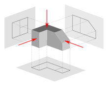
A multiview projection is a type of orthographic projection that shows the object as it looks from the front, right, left, top, bottom, or back (e.g. the primary views), and is typically positioned relative to each other according to the rules of either first-angle or third-angle projection. The origin and vector direction of the projectors (also called projection lines) differs, as explained below.
- In first-angle projection, the parallel projectors originate as if radiated from behind the viewer and pass through the 3D object to project a 2D image onto the orthogonal plane behind it. The 3D object is projected into 2D "paper" space as if you were looking at a radiograph of the object: the top view is under the front view, the right view is at the left of the front view. First-angle projection is the ISO standard and is primarily used in Europe.
- In third-angle projection, the parallel projectors originate as if radiated from the far side of the object and pass through the 3D object to project a 2D image onto the orthogonal plane in front of it. The views of the 3D object are like the panels of a box that envelopes the object, and the panels pivot as they open up flat into the plane of the drawing.[2] Thus the left view is placed on the left and the top view on the top; and the features closest to the front of the 3D object will appear closest to the front view in the drawing. Third-angle projection is primarily used in the United States and Canada, where it is the default projection system according to ASME standard ASME Y14.3M.
Until the late 19th century, first-angle projection was the norm in North America as well as Europe;[3][4] but circa the 1890s, third-angle projection spread throughout the North American engineering and manufacturing communities to the point of becoming a widely followed convention,[3][4] and it was an ASA standard by the 1950s.[4] Circa World War I, British practice was frequently mixing the use of both projection methods.[3]
As shown above, the determination of what surface constitutes the front, back, top, and bottom varies depending on the projection method used.
Not all views are necessarily used.[5] Generally only as many views are used as are necessary to convey all needed information clearly and economically.[6] The front, top, and right-side views are commonly considered the core group of views included by default,[7] but any combination of views may be used depending on the needs of the particular design. In addition to the six principal views (front, back, top, bottom, right side, left side), any auxiliary views or sections may be included as serve the purposes of part definition and its communication. View lines or section lines (lines with arrows marked "A-A", "B-B", etc.) define the direction and location of viewing or sectioning. Sometimes a note tells the reader in which zone(s) of the drawing to find the view or section.
Auxiliary views
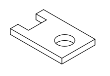
An auxiliary view is an orthographic view that is projected into any plane other than one of the six primary views.[8] These views are typically used when an object contains some sort of inclined plane. Using the auxiliary view allows for that inclined plane (and any other significant features) to be projected in their true size and shape. The true size and shape of any feature in an engineering drawing can only be known when the Line of Sight (LOS) is perpendicular to the plane being referenced. It is shown like a three-dimensional object. Auxiliary views tend to make use of axonometric projection. When existing all by themselves, auxiliary views are sometimes known as pictorials.
Isometric projection
An isometric projection shows the object from angles in which the scales along each axis of the object are equal. Isometric projection corresponds to rotation of the object by ± 45° about the vertical axis, followed by rotation of approximately ± 35.264° [= arcsin(tan(30°))] about the horizontal axis starting from an orthographic projection view. "Isometric" comes from the Greek for "same measure". One of the things that makes isometric drawings so attractive is the ease with which 60° angles can be constructed with only a compass and straightedge.
Isometric projection is a type of axonometric projection. The other two types of axonometric projection are:
Oblique projection
An oblique projection is a simple type of graphical projection used for producing pictorial, two-dimensional images of three-dimensional objects:
- it projects an image by intersecting parallel rays (projectors)
- from the three-dimensional source object with the drawing surface (projection plan).
In both oblique projection and orthographic projection, parallel lines of the source object produce parallel lines in the projected image.
Perspective projection
Perspective is an approximate representation on a flat surface, of an image as it is perceived by the eye. The two most characteristic features of perspective are that objects are drawn:
- Smaller as their distance from the observer increases
- Foreshortened: the size of an object's dimensions along the line of sight are relatively shorter than dimensions across the line of sight.
Section Views
Projected views (either Auxiliary or Multiview) which show a cross section of the source object along the specified cut plane. These views are commonly used to show internal features with more clarity than may be available using regular projections or hidden lines. In assembly drawings, hardware components (e.g. nuts, screws, washers) are typically not sectioned.
First Steps for solidworks beginner to crate 3D model
you can following this video to create simple 3D modeling [click this link] .


Comments
Post a Comment